PCIe Usage
1. Introduction to PCIe
PCIe (Peripheral Component Interconnect Express) is a high-speed serial interface standard used to connect the motherboard and external devices. It is the successor to the PCI technology, aiming to provide higher bandwidth and better performance.
- High-speed transmission: The PCIe interface provides a high-speed data transmission channel that can be used to connect various hardware devices such as graphics cards, storage devices, network adapters, etc. Its speed is typically expressed in the number of data bits transferred per second (e.g., PCIe x1, x4, x8, x16, etc.), and the bandwidth of each channel can be expanded as needed.
- Point-to-point connection: PCIe adopts a point-to-point connection architecture, meaning that each device is directly connected to the PCIe slot on the motherboard, without sharing bandwidth with other devices. This helps reduce latency and improve performance.
- Hot-plug support: The PCIe interface supports hot-plugging, allowing users to add or remove PCIe devices while the computer is running, without the need to reboot the computer.
- Wide application: The PCIe interface is widely used to connect graphics cards, solid-state drives (SSDs), expansion cards, network adapters, and other high-performance devices. This allows computer users to expand and upgrade the system's performance and functionality as needed.
In summary, PCIe is a high-speed, flexible, and widely-used serial interface standard that plays a critical role in modern computer systems, providing a reliable solution for connecting various external devices.
2. PCIe Controllers on RK3588
- RK3588 has a total of 5 PCIe controllers, with the same hardware IP but different configurations. One of them is a 4-Lane DM mode that can support being used as an EP, while the other 2-Lane and 3 1-Lane controllers can only be used as RCs.
- RK3588 has two types of PCIe PHYs, one of which is a PCIe 3.0 PHY with 2 ports and 4 lanes, while the other is a PCIe 2.0 PHY with 3 ports, each being a 2.0 1-Lane combined with SATA and USB.
- The 4 lanes of the PCIe 3.0 PHY can be split according to actual needs, and after splitting, the corresponding controller needs to be configured reasonably. All configurations are done in the DTS without the need to modify the driver.
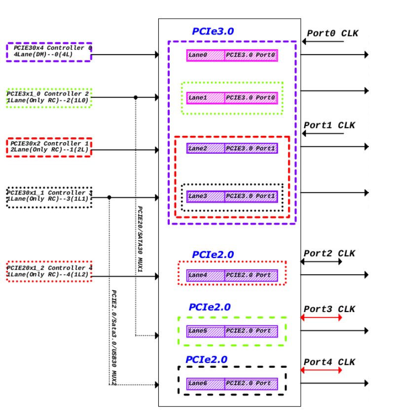
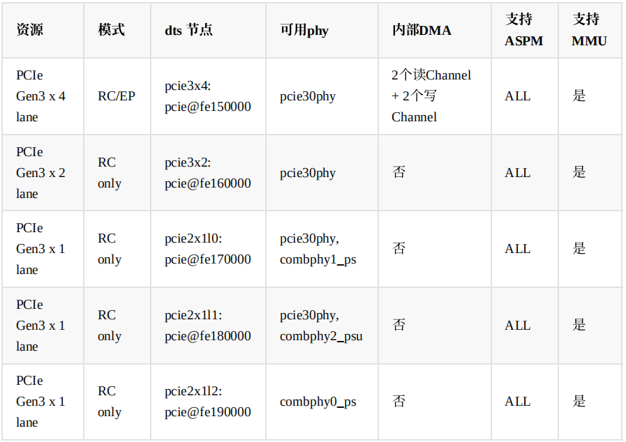
The hardware resources of RK3588 PCIe and the corresponding relationships between the PCIe controller nodes and PHY nodes in software are shown in the following figure:
3. RK3588 DTS Configuration
3.1 PCIe Interfaces on ArmSoM-W3
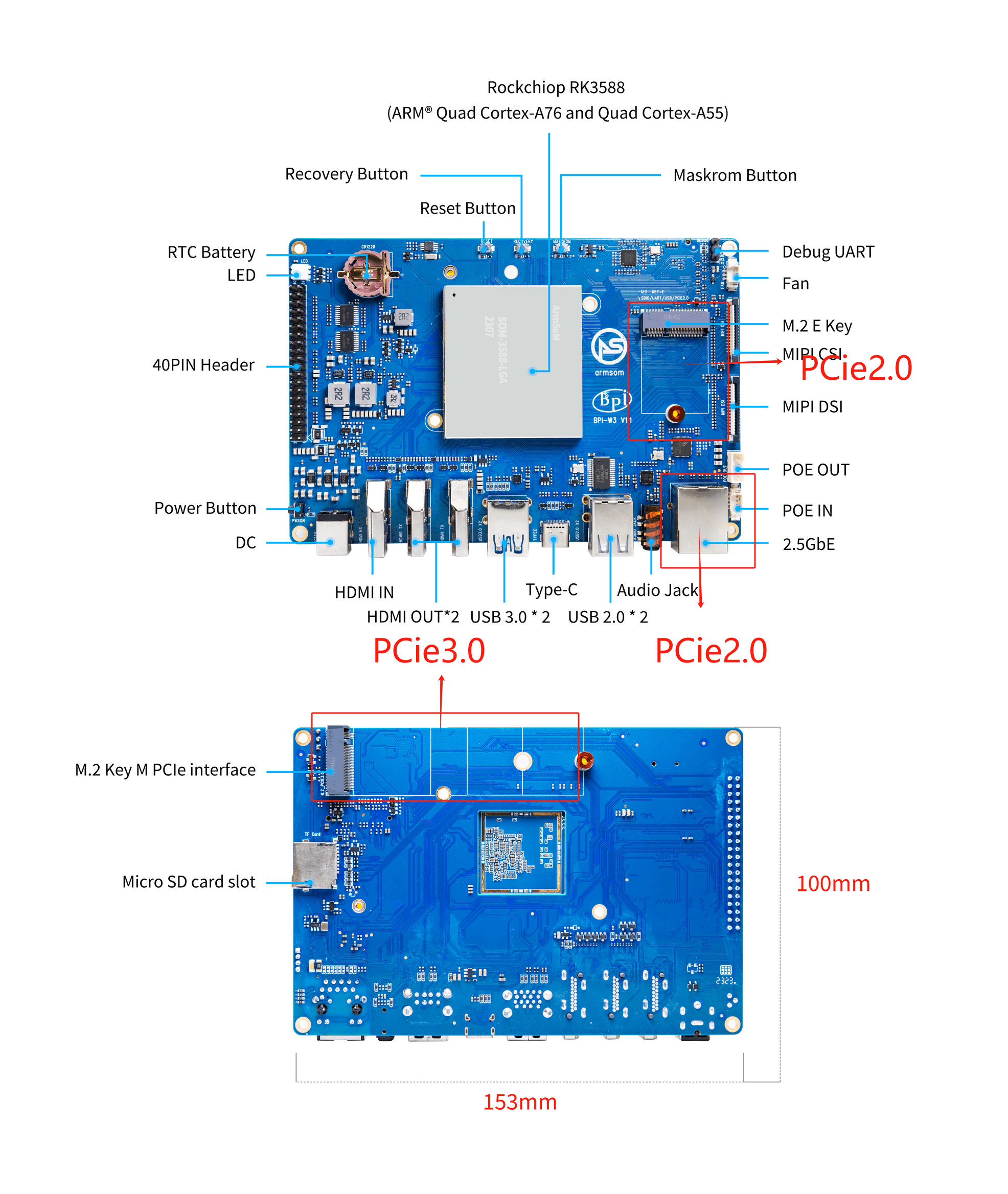
- Here, we use the ArmSoM-W3 development board as an example to explain the PCIe configuration of RK3588.
- The ArmSoM-W3 development board has 1 PCIe 3.0 x4 interface and two PCIe 2.0 interfaces, as shown in the figure:
3.2 PCIe-related DTS Configuration on the ArmSoM-W3 Development Board:
Generally, according to the schematic diagram, the power supply pins, reset pins, and the correct PCIe controller node and PHY node are configured in the DTS.
- In kernel/arch/arm64/boot/dts/rockchip/rk3588-armsom-w3.dts, configure as follows:
/ {
    vcc12v_dcin: vcc12v-dcin {
        compatible = "regulator-fixed";
        regulator-name = "vcc12v_dcin";
        regulator-always-on;
        regulator-boot-on;
        regulator-min-microvolt = <12000000>;
        regulator-max-microvolt = <12000000>;
    };

    vcc5v0_sys: vcc5v0-sys {
        compatible = "regulator-fixed";
        regulator-name = "vcc5v0_sys";
        regulator-always-on;
        regulator-boot-on;
        regulator-min-microvolt = <5000000>;
        regulator-max-microvolt = <5000000>;
        vin-supply = <&vcc12v_dcin>;
    };

    vcc3v3_pcie2x1l0: vcc3v3-pcie2x1l0 {
        compatible = "regulator-fixed";
        regulator-name = "vcc3v3_pcie2x1l0";
        regulator-min-microvolt = <3300000>;
        regulator-max-microvolt = <3300000>;
        enable-active-high;
        regulator-boot-on;
        regulator-always-on;
        gpios = <&gpio1 RK_PD2 GPIO_ACTIVE_HIGH>;
        startup-delay-us = <50000>;
        vin-supply = <&vcc5v0_sys>;
    };

    vcc3v3_pcie2x1l2: vcc3v3-pcie2x1l2 {
        compatible = "regulator-fixed";
        regulator-name = "vcc3v3_pcie2x1l2";
        regulator-min-microvolt = <3300000>;
        regulator-max-microvolt = <3300000>;
        startup-delay-us = <5000>;
        vin-supply = <&vcc_3v3_s3>;
    };

    vcc3v3_pcie30: vcc3v3-pcie30 {
        compatible = "regulator-fixed";
        regulator-name = "vcc3v3_pcie30";
        regulator-min-microvolt = <3300000>;
        regulator-max-microvolt = <3300000>;
        enable-active-high;
        gpios = <&gpio1 RK_PA4 GPIO_ACTIVE_HIGH>;
        startup-delay-us = <5000>;
        vin-supply = <&vcc5v0_sys>;
    };
}

&pcie2x1l0 {
    reset-gpios = <&gpio4 RK_PA5 GPIO_ACTIVE_HIGH>;
    vpcie3v3-supply = <&vcc3v3_pcie2x1l0>;
    status = "okay";
};

&pcie2x1l2 {
    reset-gpios = <&gpio3 RK_PB0 GPIO_ACTIVE_HIGH>;
    vpcie3v3-supply = <&vcc3v3_pcie2x1l2>;
    status = "okay";
};

&combphy1_ps {
    status = "okay";
};

&pcie30phy {
    rockchip,pcie30-phymode = <PHY_MODE_PCIE_AGGREGATION>;
    status = "okay";
};

&pcie3x4 {
    reset-gpios = <&gpio4 RK_PB6 GPIO_ACTIVE_HIGH>;
    vpcie3v3-supply = <&vcc3v3_pcie30>;
    status = "okay";
};
pcie30phy, combphy1_ps: PHY nodes
pcie3x4, pcie2x1l0, pcie2x1l2: PCIe controller nodes
reset-gpios: Reset pin attribute
vcc3v3_pcie2x1l0, vcc3v3_pcie2x1l2, vcc3v3_pcie30: Power supply pin nodes
4. How to Use PCIe Devices
Executing the lspci command will list information about all PCI devices, including the manufacturer, model, PCI address, etc. The output is typically provided in text form and sorted in order of bus address (BDF: Bus, Device, Function).
armsom@armsom:~$ lspci
0000:00:00.0 PCI bridge: Rockchip Electronics Co., Ltd Device 3588 (rev 01)
0000:01:00.0 Non-Volatile memory controller: Intel Corporation NVMe Optane Memory Series
0002:20:00.0 PCI bridge: Rockchip Electronics Co., Ltd Device 3588 (rev 01)
0002:21:00.0 Ethernet controller: Realtek Semiconductor Co., Ltd. RTL8125 2.5GbE Controller (rev 05)
0003:30:00.0 PCI bridge: Rockchip Electronics Co., Ltd Device 3588 (rev 01)
0003:31:00.0 Network controller: Broadcom Inc. and subsidiaries Device 449d (rev 02)
0004:40:00.0 PCI bridge: Rockchip Electronics Co., Ltd Device 3588 (rev 01)
0004:41:00.0 Ethernet controller: Realtek Semiconductor Co., Ltd. RTL8125 2.5GbE Controller (rev 05)
The PCIe interface is commonly used to connect high-speed solid-state drives (SSDs). Here, we use the Non-Volatile Memory (NVMe) controller produced by Intel Corporation as an example to explain the usage of the NVMe controller.
4.1 Using the NVMe Controller
- Check if the NVMe device is recognized:
- Run the following command to check if the system correctly recognizes the NVMe device:
armsom@armsom:/$  lspci | grep NVMe
0000:01:00.0 Non-Volatile memory controller: Intel Corporation NVMe Optane Memory Series
If you see information about an NVMe device related to Intel Corporation, it means the device has been recognized.
- Find the device node:
ls /dev/nvme*
/dev/nvme0  /dev/nvme0n1
- View the partition information of the device:
armsom@armsom:/$ lsblk
NAME         MAJ:MIN RM  SIZE RO TYPE MOUNTPOINTS
mmcblk0      179:0    0 58.3G  0 disk
├─mmcblk0p1  179:1    0    4M  0 part
├─mmcblk0p2  179:2    0    4M  0 part
├─mmcblk0p3  179:3    0   64M  0 part
├─mmcblk0p4  179:4    0  128M  0 part
├─mmcblk0p5  179:5    0   32M  0 part
├─mmcblk0p6  179:6    0   14G  0 part
├─mmcblk0p7  179:7    0  128M  0 part
└─mmcblk0p8  179:8    0 43.9G  0 part
mmcblk0boot0 179:32   0    4M  1 disk
mmcblk0boot1 179:64   0    4M  1 disk
mmcblk1      179:96   0 29.7G  0 disk
├─mmcblk1p1  179:97   0  512M  0 part /boot/firmware
└─mmcblk1p2  179:98   0 29.2G  0 part /
nvme0n1      259:0    0 13.4G  0 disk /mnt
NVMe devices are typically represented in the format /dev/nvmeXnY, where X is the number of the NVMe device, and Y is the partition number. In this case, the NVMe device name is nvme0n1.
- Format as EXT4 file system (run the formatting operation according to your needs)
sudo mkfs.ext4 /dev/nvme0n1
- Mount the device
armsom@armsom:~$ sudo mount /dev/nvme0n1 /mnt
- View the mount path
df -h
/dev/nvme0n1     14G   24K   13G   1% /mnt
or
cat /proc/mounts  | grep nvme
/dev/nvme0n1 /mnt ext4 rw,relatime 0 0
- Unmount the device
umount /mnt
4.2 Read and Write Speed Test
Use the dd command for read and write testing:
- Write test command:
sudo dd if=/dev/zero of=/dev/nvme0n1 bs=1M count=1000
The if parameter is the input file (usually /dev/zero, used for write testing), the of parameter is the output file (usually your NVMe device), the bs parameter is the block size, and the count parameter is the number of blocks to execute.
- Read test command:
sudo dd if=/dev/nvme0n1 of=/dev/null bs=1M count=1000
The read and write performance may be affected by various factors, including the device model, hardware configuration, and test conditions.